Object3D
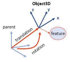
An Object3D constructor is the core element of Modia3D. It defines a coordinate system moving in 3D together with associated features like Scene, Visual and Solid:
Modia3D.Composition.Object3D — TypeObject3D(;
parent = nothing,
fixedToParent = true,
translation = [0.0, 0.0, 0.0],
rotation = [0.0, 0.0, 0.0],
velocity = [0.0, 0.0, 0.0],
angularVelocity = [0.0, 0.0, 0.0],
feature = nothing)Generate a new Object3D object, that is a coordinate system with associated feature that is described relatively to its (optional) parent Object3D.
Vectors translation, rotation, velocity, angularVelocity can be defined with units from package Unitful. If no units are provided, SI units are assumed (internally, all computations are performed with SI units, that is in m, rad, m/s, rad/s).
Arguments
parent: Parent Object3D. Ifparentis present, the Object3D is defined relatively toparent. Ifparent=nothing, the Object3D is either the inertial system (typically calledworld), or the object is the reference system of a sub-system (via joints, all sub-systems must be connected directly or indirectly toworld). Argumentstranslation,rotation,velocity,angularVelocityare ignored in this case (a warning is printed, if these arguments do not have zero values).fixedToParent: = true, if Object3D is fixed relatively toparent. Otherwise, Object3D can move freely relatively to parent (translation,rotation,velocity,angularVelocityis the initial state of Object3D with respect toparent). Ifparent=nothing, thenfixedToParentis ignored.translation: Vector from the origin of the parent to the origin of the Object3D, resolved in the parent coordinate system.
Example:translation = [0.0, 0.5, 0.0]ortranslation = [0.0, 50.0, 0.0]u"cm"are a relative translation of 0.5 m in y-direction of the parent.rotation: Vector[angleX, angleY, angleZ]to rotate the parent coordinate system along the x-axis withangleX, the y-axis withangleYand the z-axis withangleZto arrive at the Object3D coordinate system.
Example:rotation = [0.0, pi/2, 0.0]orrotation = [0.0, 90u"°", 0.0]defines that a rotation around the y-axis of the parent coordinate system with 90 degrees arrives at the Object3D.velocity: Ifparentis defined andfixedToParent=false, the initial velocity of the origin of the Object3D with respect to theparent, resolved in the parent coordinate system.
Example:velocity = [0.0, 0.5, 0.0]orvelocity = [0.0, 50.0, 0.0]u"cm/s"is an initial relative velocity of 0.5 m/s in y-direction of the parent.angularVelocity: Ifparentis defined andfixedToParent=false, the initial angular velocity of the Object3D with respect to theparent, resolved in the parent coordinate system.
Example:angularVelocity = [0.0, pi/2, 0.0]orangularVelocity = [0.0, 90u"°/s", 0.0]is an initial relative angular velocity of 90 degrees per second in y-direction of the parent.feature: Defines the (optional) property associated with the Object3D by a constructor call. Supported constructors:Scene: A Scene feature marks the root Object3D (world, origin, inertial system). It has no parent Object3D and allows to define global properties, such as the gravity field.Visual: A Visual feature defines a shape used for visualization.Solid: A Solid feature defines the solid properties of an Object3D, like mass, inertia tensor, collision behavior.nothing: No feature is associated with the Object3D. This might be useful for helper Object3Ds, for example to mark a point on a shape and connecting it later via a joint.
States, if freely moving
If fixedToParent=false, the Object3D is moving freely relatively to parent. Vectors translation, rotation, velocity, angularVelocity (all resolved in parent) are used as states and are available in the result for plotting.
If rotation[2] is close to its singular position (= 90u"°" or -90u"°"), an event is triggered and the rotation sequence is changed from [angleX, angleY, angleZ] to [angleX, angleZ, angleY]. In the new rotation sequence, rotation[2] is far from its singular position at this time instant. Variable rotationXYZ::Bool in the result signals whether rotation is defined with rotation sequence [angleX, angleY, angleZ] (rotationXYZ=true) or with rotation sequence [angleX, angleZ, angleY] (rotationXYZ=false). See, example Modia3D/test/Basic/ShaftFreeMotionAdaptiveRotSequence.jl. The initial conditions (so rotation=... as key/value pair in the Object3D constructor) are always with rotationXYZ=true. With respect to an approach where the rotation is described with quaternions, the adaptive rotation sequence handling has the benefit that all integrators can be used (a quaternion description works with an overdetermined set of states and therefore standard integrators with step size control need non-trivial code changes).
Example
using Modia3D

model = Model3D(
    world      = Object3D(feature = Scene()),
    worldFrame = Object3D(parent  = :world,
                          feature = Visual(shape=CoordinateSystem())),
    support    = Object3D(parent  = :world, translation = [0.0, 0.5, 0.0],
                          feature = Visual(shape = Sphere(diameter=0.1)))
)A feature defines a property that is associated with an Object3D. Currently, the following features are supported:
Scene
Modia3D.Composition.Scene — TypeScene(; kwargs...)Defines global properties of the system, such as the gravity field. Exactly one Object3D must have a Scene feature defined. This Object3D is used as root Object3D (world, origin, inertial system) and is not allowed to have a parent Object3D.
| Keyword arguments | defaults |
|---|---|
gravityField | UniformGravity(g=9.81, n=[0,-1,0]) |
enableVisualization | true |
animationFile | nothing |
provideAnimationHistory | false |
enableContactDetection | true |
elasticContactReductionFactor | 1.0 (> 0.0, <= 1.0) |
maximumContactDamping | 2000.0 |
mprTolerance | 1.0e-20 |
mprIterMax | 120 |
visualizeFrames | false |
visualizeBoundingBox | false |
visualizeContactPoints | false |
visualizeSupportPoints | false |
nominalLength | 1.0 |
defaultFrameLength | 0.2*nominalLength |
nVisualContSupPoints | 5 |
defaultContactSphereDiameter | 0.1 |
cameraDistance | 10.0*nominalLength |
cameraLongitude | 30/180*pi |
cameraLatitude | 15/180*pi |
lightDistance | 10.0*nominalLength |
lightLongitude | 60/180*pi |
lightLatitude | 45/180*pi |
useOptimizedStructure | true |
Arguments
gravityField::Modia3D.AbstractGravityField: Gravity field of the scene. Supported values:enableVisualization::Bool: = true, to enable online animation with DLR SimVis. If SimVis is not installed, this flag has no effect.animationFile::String: After termination of the simulation, store animation in json-file that can be imported into the open source 3D editor threejs.org. Example:animationFile = "animation.json".enableContactDetection::Bool: = true, if contact detection is enabled, see Collision Handling.elasticContactReductionFactor::Float64(> 0.0, <= 1.0):usedContactCompliance = contactCompliance * elasticContactReductionFactor. For more details, see Material constants.maximumContactDamping(> 0.0): Maximum damping factor for elastic contacts. For more details, see Damping coefficient.mprTolerance::1.0e-20: Local tolerance used for terminating the mpr algorithm (that computes the distances between shapes). Changing this value might improve speed. For integrators with step-size control, a value is needed that is much smaller as the relative tolerance used for the integration.mprIterMax::120: Local maximum amount of iterations used for mpr algorithm. If more iterations are needed a message is printed.visualizeFrames::Bool: = true, to visualize the coordinate system of every Object3D that is not explicitly switched off.visualizeBoundingBox::Bool: Flag enabled for visualizing Axis Aligned Bounding Box (AABB) for all solid shapes allowed to collidevisualizeContactPoints::Bool: Flag enabled for visualizing contact points, andenableVisualization = truevisualizeSupportPoints::Bool: Flag enabled for visualizing support points, andenableVisualization = truenominalLength::Float64: Nominal length in [m].defaultFrameLength::Float64: Default frame length in [m] for visualizing little CoordinateSystem.nVisualContSupPoints::Int64: Defines how many contact as well as support points are visualized (there is a warning if you'll need to increase it)defaultContactSphereDiameter::Float64: Diameter of Sphere in [m] used for contact and support point visualizationcameraDistance::Float64: Distance between world frame and camera position (animation export only)cameraLongitude::Float64: Longitude angle of camera position (0 = -y/-z/-x direction) (animation export only)cameraLatitude::Float64: Latitude angle of camera position (0 = horizontal) (animation export only)lightDistance::Float64: Distance between world frame and light position (animation export only)lightLongitude::Float64: Longitude angle of light position (0 = -y/-z/-x direction) (animation export only)lightLatitude::Float64: Latitude angle of light position (0 = horizontal) (animation export only)useOptimizedStructure::Bool: = true, if pre-processing the whole system. For example, computing the common mass, common center of mass and common inertia tensor of all rigidly connected Object3Ds that have mass properties.
Solid
Modia3D.Shapes.Solid — TypeSolid(; shape = nothing,
solidMaterial = nothing,
massProperties = nothing,
visualMaterial = VisualMaterial(),
collision = false,
contactMaterial = "",
collisionSmoothingRadius = 0.001,
contactSphereRadius = nothing)Generate a Solid with physical behavior of a rigid body with mass, visualization and collision properties. Solid is used as feature of an Object3D.
Arguments
shape: Defines the shape of the solid. Only Shapes from –– For Solid and Visual –– can be used. If undefined the solid is not considered in visualization or Collision Handling andmassPropertiesmust be explicitly defined.solidMaterial: Defines the material of the solid used for mass properties computation and (ifcontactMaterialis undefined) contact force calculation. A pre-defined Solid material from palettes/solidMaterials.json (e.g."Steel") or a user-defined Solid material (e.g.SolidMaterial(density=7850)) can be used.solidMaterial = ""is treated assolidMaterial = nothing.massProperties: Defines the mass properties of the solid.massProperties = nothing: The mass properties are computed fromshapeandsolidMaterial. If additionallysolidMaterial = nothing, the solid is treated as massless.massProperties = MassProperties(; mass=0.0, centerOfMass=[0.0,0.0,0.0], Ixx=0.0, Iyy=0.0, Izz=0.0) Ixy=4.5, Ixz=4.6, Iyz=5.5): Defines all mass properties explicitlyMassProperties()defines a massless solid.massProperties = MassPropertiesFromShapeAndMass(; mass=0.0): The center of mass and the inertia tensor is computed fromshapeand frommass.
visualMaterial: Defines the material of the solid used for visualization. A pre-defined Visual material from palettes/visualMaterials.json (e.g.visualMaterial = "RedTransparent") or a user-defined Visual material (e.g.VisualMaterial(color="DeepSkyBlue4", transparency=0.75)) can be used. Note,VisualMaterial = ""is treated asvisualMaterial = VisualMaterial(), so using the default visual material.collision: Defines if the solid is considered in Collision Handling.collision=truerequires definition ofshapeand of contact material (defined bysolidMaterialorcontactMaterial).contactMaterial: Defines the contact material in case of collision. For details, see Contact Force Law (e.g."Steel"). If undefinedsolidMaterialis used as contact material. Only contact material combinations defined in palettes/contactPairMaterials.json can be used.collisionSmoothingRadius: Defines a collision smoothing radius for surface edges, its default value is0.001[m]. This improves the robustness of the integration, if contact is on or close to a surface edge. It takes the minimum value of the provided collision smoothing radius and 10% of the smallest shape length, likemin(collisionSmoothingRadius, 0.1 min(shape dimensions)). If it is set to0.0nocollisionSmoothingRadiusis used. AcollisionSmoothingRadiusis used forBox,Cylinder,Cone, andBeam.contactSphereRadius: For each shape acontactSphereRadiusis defined, so that a rough approximiation of Hertz' pressure is used in Response calculation not only for spheres. You can define your owncontactSphereRadius, otherwise it is computed from shape geometry (sketched in the following table).
| Shape | contactSphereRadius from shape |
|---|---|
| Sphere | diameter/2 |
| Ellipsoid | min(lengthX, lengthY, lengthZ)/2 |
| Box | min(lengthX, lengthY, lengthZ)/2 |
| Cylinder | min(diameter, length)/2 |
| Cone | (diameter + topDiameter)/4 |
| Capsule | diameter/2 |
| Beam | min(length, width, thickness)/2 |
| FileMesh | shortestEdge/2 |
For flat shapes, Box and Beam, no contactSphereRadius is taken. For Herz' pressure it is needed only if two flat shapes are colliding. Note, contactSphereRadius <= 0 is treated as contactSphereRadius = nothing, so is computed from the table above.
Example
using Modia3D

Solid(; shape = Sphere(diameter=0.5),
        solidMaterial = "DryWood",
        collision = true,
        contactMaterial = "Steel",
        collisionSmoothingRadius = 0.001,
visualMaterial = VisualMaterial(color="DarkViolet"))Examples for Solids
How to compute or define mass properties?
# [M1]: mass properties are computed via shape geometry and predefined solidMaterial
# with defined density, this is the default setting
Solid(shape = Sphere(diameter=0.5), solidMaterial = "Steel")

# [M2]: mass properties are computed via shape geometry and a defined mass
Solid(shape = Sphere(diameter=0.5), massProperties = MassPropertiesFromShapeAndMass(mass=4.5))

# [M3]: mass properties are explicitly defined: with mass, center of mass, inertia matrix.
# For this option a shape and solidMaterial are optional.
Solid(massProperties = MassProperties(mass=2.0, centerOfMass=[1,2,3],
      Ixx=3.0, Iyy=4.0, Izz=4.0, Ixy=6.0, Ixz=7.0, Iyz=9.0) )
How to define Solids for Collision Handling? You always have to enable collision flag, and define a shape geometry. Make sure mass properties are computed and define how it behaves in contact situations.
# mass properties are computed like in [M1]
# it behaves like "Steel" in contact situations
Solid(shape = Sphere(diameter=0.5), solidMaterial = "Steel", collision = true)

# mass properties are computed like in [M1]
# it behaves like "DryWood" in contact situations
Solid(shape = Sphere(diameter=0.5), solidMaterial = "Steel", collision = true,
      contactMaterial = "DryWood")

# mass properties are computed like in [M2]
# it behaves like "Steel" in contact situations
Solid(shape = Sphere(diameter=0.5),
      massProperties = MassPropertiesFromShapeAndMass(mass=4.5),
      solidMaterial = "Steel", collision = true)

# mass properties are explicitly given like in [M3]
# it behaves like "Steel" in contact situations
Solid(shape = Sphere(diameter=0.5),
      massProperties = MassProperties(mass=2.0, centerOfMass=[1,2,3],
      Ixx=3.0, Iyy=4.0, Izz=4.0, Ixy=6.0, Ixz=7.0, Iyz=9.0),
      solidMaterial = "Steel", collision = true)
The following functions are provided for a Solid shape that is associated with an Object3D
| Function | Description |
|---|---|
volume(shape) | volume computation |
inertiaMatrix(shape, mass) | returns inertia matrix of solid with respect to reference Object3D |
centroid(shape) | center of mass |
hasMass(object3D) | check if a shape has mass properties |
canCollide(object3D) | checks if collision flag is enabled |
boundingBox(shape, <other arguments>) | bounding box - broad phase of Collision Handling |
supportPoint(shape, <other arguments>) | needed for narrow phase of Collision Handling |
| further functions | ... |
Visual
Modia3D.Shapes.Visual — TypeVisual(; shape = nothing,
visualMaterial = VisualMaterial())Generate a new visual shape with a visual material. It is only for visualizing, without physical behavior. The default is no shape and a default visual material.
Arguments
shape: It is possible to use all Shapes from both sets visual and solid, e.g.Sphere,Box,CoordinateSystem. The default value isnothing, this means it will not be visualized.visualMaterial: Defines the material of the shape used for visualization. A pre-defined Visual material from palettes/visualMaterials.json (e.g.visualMaterial = "RedTransparent") or a user-defined Visual material (e.g.VisualMaterial(color="DeepSkyBlue4", transparency=0.75)) can be used. Note,VisualMaterial = ""is treated asvisualMaterial = VisualMaterial(), so using the default visual material.
Examples
using Modia3D

shape1 = Visual(shape = Sphere(diameter = 0.5),
                visualMaterial = VisualMaterial(color = "Green"));
shape2 = Visual(shape = Sphere(diameter = 0.5),
visualMaterial = "GreenTransparent");An Object3D is visible in visualization and animation export if a shape and a visualMaterial are defined.
Examples for displaying Solid and Visual features
Visual features
# a visual shape is displayed with a user defined visual material
Visual(shape = Sphere(diameter=0.5), visualMaterial = VisualMaterial(color = "goldenrod1"))

# a visual shape is displayed with a default visual material
Visual(shape = Sphere(diameter=0.5))
Solid features
# a solid shape is displayed with a user defined visual material
Solid(shape = Sphere(diameter=0.5), visualMaterial = VisualMaterial(color = "aquamarine4"))

# a solid shape is displayed with a user defined visual material
Solid(shape = Sphere(diameter=0.5))

# this solid shape is NOT displayed
Solid(shape = Sphere(diameter=0.5), visualMaterial = nothing)